ALLIANCE JC50CG Specifications Page 44
- Page / 60
- Table of contents
- BOOKMARKS
- Drying Tumblers 1
- MISE EN GARDE 3
- Table of 4
- Contents 4
- Introduction 6
- Serial Plate Location 7
- Save These Instructions 9
- Important Safety Instructions 9
- Safety Information 10
- Specifications and Dimensions 11
- Cabinet Dimensions 12
- Exhaust Outlet Locations 13
- Gas Connection Locations 14
- GAS AND STEAM ELECTRIC 15
- Steam Connection Locations 16
- Installation 17
- Location Requirements 18
- 70256801 19
- Figure 3 20
- Models Only 22
- General Information 23
- Basic Configuration 24
- Unregulated 24
- Figure 6 25
- Figure 7 26
- Figure 8 26
- Tabl e 3 27
- Tabl e 4 28
- Tabl e 5 29
- Figure 9 30
- Exhaust Requirements 31
- Individual Venting 32
- Manifold Venting 33
- Gas Requirements 35
- Figure 13 36
- Figure 14 37
- High Altitude Orifice Sizing 39
- Steam Requirements 40
- Condensate Return Connections 41
- Electrical Requirements 43
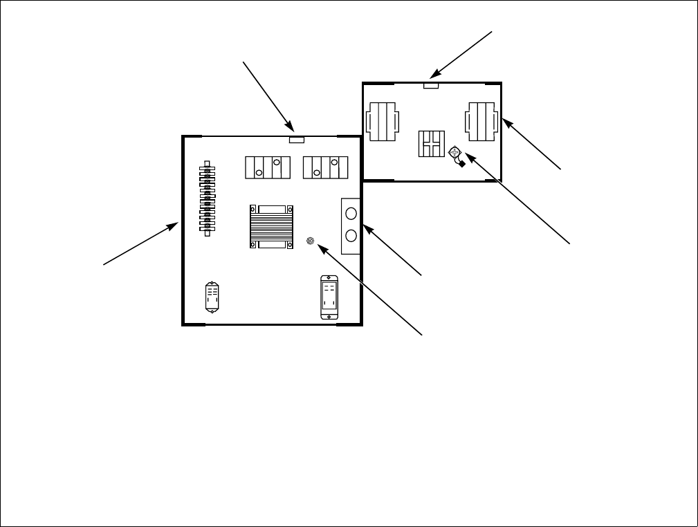
- Figure 16 44
- Ferrite Ring Installation 45
- 50 Pound Tumbler Electrical 46
- Requirements 46
- 75 Pound Tumbler Electrical 47
- Adjustments 48
- Airflow Switch 49
- Figure 19 50
- Loading Door Switch 51
- Figure 21 52
- Loading Door Strike 53
- Chain Drive 54
- Belt Drive 55
- Figure 23 56
- Figure 24 57
- Figure 25 58
- Figure 26 59
- Removing Tumbler from Service 60
Related products and manuals for Tumble dryers ALLIANCE JC50CG
 (63 pages)
© 2020, manymanuals.com. All rights reserved. | 2.898 s |
 Manymanuals.com
 Manymanuals.de
 Manymanuals.fr
 Manymanuals.it
 Manymanuals.pl
 Manymanuals.cz
 Manymanuals.es
 Manymanuals-pt.com
Comments to this Manuals